
Tagged: AFE
ABB literature FACT CHECK
We came across ABBs brochure for the ACS880 Ultra Low Harmonic and Regen Drives which is ABBs Active Front End solutions. We noted that someone has been very imaginative on a level where it is necessary to point it out. Surprising for such a well renown market leader.
What are we talking about?
Below is a snapshot from ABBs brochure for the ACS880 highlighting the incredible advantage of using Active Front End(AFE) drives instead of using passive or active filters. The main point being that the AFE has a much higher system efficiency than Active Harmonic Filters(AHF) and Passive Harmonic Filters(PHF) while maintaining a very high THD-reduction.
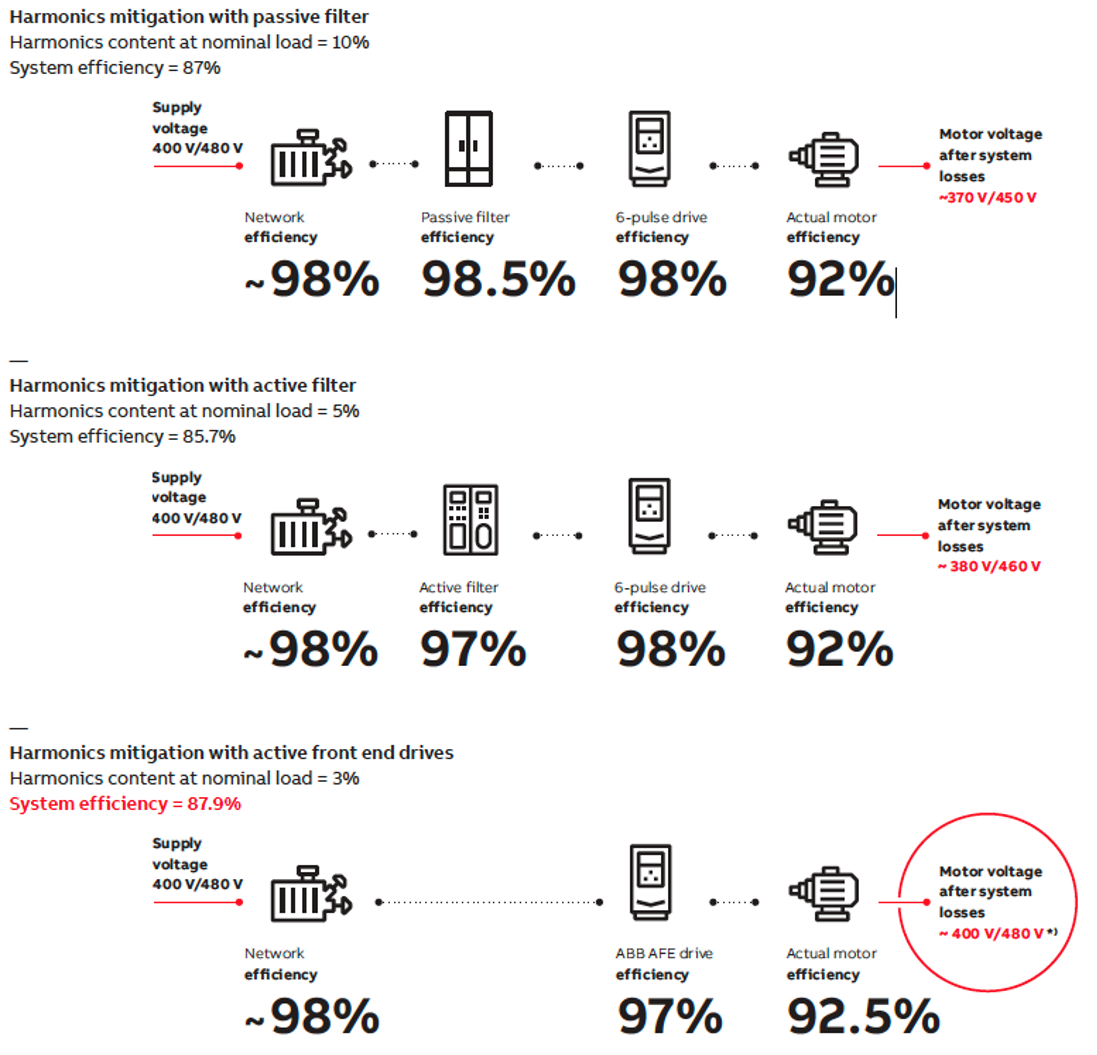
Figure 1: Snapshot from ABBs brochure in question.
So what is wrong?
Well, lets start with the AFE efficiency of 97%. Sounds fantastic, as an AFE is 2 x inverter +1x LCL filter it sounds incredible. Which it is. Theoretical losses should be roughly 2×1,2+2% so maximum 96,6%. There is an easier way to verify this and that is to actually check ABBs own datasheet for the ACS880.
An 250 kW ACS880-UHD has 11 kW losses through heat. That is 4.4% or an efficiency of 95.6% far from the 97% stated. To be fair a wall mounted 110 kW AFE is rated at 3.5% losses indicating 96.5% efficiency but still well below 97%.
So AFE system efficiency is 95.6-96.5% at optimum.
Secondly they are making a big deal that a 6-pulse drive create a significant voltage drop which in turn reduce the motor efficiency. Based on the numbers this must be an AC-choke they are using. Most drives are outfitted with DC-chokes with significantly less voltage drop. It is correct that a passive serial filter cause a voltage drop. An Active Filter being placed in parallel does not cause a voltage drop.
So, once again lets go back to the ACS880 6p version which is equipped with a dc-choke as standard. A 250 kW 6 P ACS 880 has 1,7-2,4% losses (wall/cabinet). So 98% is a good average.
Thirdly, most blatantly to us Active Filter Aficionados they have placed the Active Filter in a serial configuration!? Thus assuming that the Active Filter is sized 100% to load just like the Front End. In reality a typical active filter is placed in parallel with the load and sized based on the THD-load or roughly 25-33% of the load.
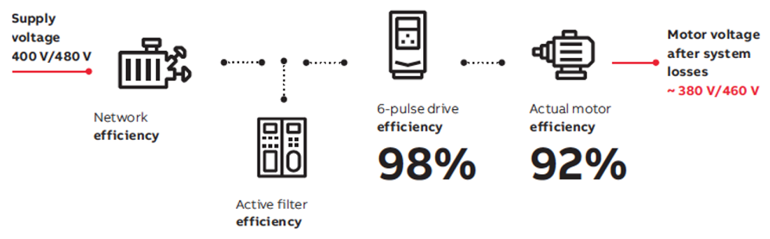
Figure 2: We helped ABB marketing correct the system topology. AHF sizing only focus on THD-level.
Using a Comsys ADF P100 as reference of an modern Active Harmonic Filter, it has 97.4% efficiency or 2.6% losses according to their datasheet.
So the AHF system losses will be 0.25-0.33 * 2.6 = 0.65-0.86% or 99.14-99.35% for simplicity we use AHF system size to be 30% of load or 99.22% system efficiency.
Updated system efficiencies:
Active Filter
Network Active Filter 6-P Drive Motor System Efficiency
98% 99.22% 98% 92%* 87.6%
*) The voltage drop across a 6P drive should be somewhere <6 V + any reactor loss if installed thus much smaller motor loss difference than suggested here. We do not have good data however and leave it as it is.
ACS 880 AFE
Network AFE Drive Motor System Efficiency
98% 95.6-96.5% 92.5% 86.7-87.5%
Difference AHF vs AFE = 0.9 -0.1 %
Conclusion
So the Active Filter Configuration system efficiency is actually on par or slightly better than the ACS880 at full load.
That is without AHF sleep mode, modularity and other complimentary solutions available to Active Filters. At part load things get even worse for the AFE but that is a story for another post.
