
Category: STATCOM
Low Voltage Active Filter as a Medium Voltage STATCOM for Windpower

Kville power station compenstated by Comsys STATCOM design.
When the 32 MW Kville wind power station was being built in Sweden, the local grid owner Fortum was looking for alternatives for inductive compensation. The long underground cable length cause a dynamic capacitive reactive power problem that normally is compensated using a large MV inductor. The inductor is very large and costly device at these sizes and Fortum wished to investigate other alternatives.
Comsys used its extensive knowledge from MV applications in applying its liquid cooled low voltage Active Filter with a step up transformer to create a 2,5 MVA STATCOM solution to solve the problem. If applied correctly, an active technology is very compact and flexible enabling high availability. Comsys liquid cooled modular design offers a high degree of redundancy and availability as the modules can be operated individually.
A further complication was the requirement to measure at the PCC on the 130 kV level so the Low Voltage ADF STATCOM worked through two step-up transformers. After extensive simulations by Comsys, the system was designed and supplied through the turn key integrator Siemens.
Comsys P700 modular STATCOM solution
The active filters where installed in an existing building and the step-up transformer was installed outside, saving valuable indoor space and requiring no additional transformer cooling.
The solution dynamically compensates the capacitive reactive power and keeps it in line with the utility’s requirement. Due to the STATCOM following the load dynamically and observing both voltage and current, optimal grid conditions are ensured during all operating conditions.
The investment cost was reported to be lower than using the customized inductor solution proving the competitiveness of small active STATCOM versus passive options.
The ADF P700 STATCOM is a perfect solution in a dynamic environment such as wind farms. It is as cost effective and compact as a passive solution but with superior performance.
Active Harmonic Filters – Buyer’s Guide
Active Harmonic Filters are growing in popularity as a method to mitigate power quality issues. There are several factors to consider when specifying an active harmonic filter. Typical applications for active filters are compensation of variable frequency drives and data-centers to reduce the load on UPS systems or compensating the effects of renewable energy sources on the grid.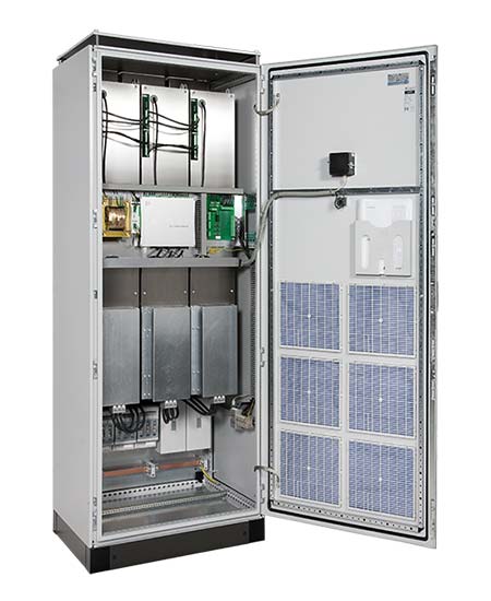
What is an Active Harmonic Filter and what is its Application.
The general definition to describe this application is an analog or digital device that measures the power quality on the grid side. It then injects current to compensate any unwanted deviations from the standard 50 or 60 Hz supply. Deviations can be mitigated in full or partially.
What Factors to Consider when Specifying an Active Harmonic Filter
Sensor or sensorless control
There are suppliers that provide sensorless control eliminating the need for current transformers. This solution reduce the installation cost. Sensorless is not used in all applications so make sure to check the application with the supplier. Sensorless control or voltage control as it is sometimes defined compensates the total THD. It is not possible to select a single source such as a single VFD. On the plus-side it is possible to protect a sensitive subgrid from a noisy primary grid.
Losses
Depending on design, the filter has higher or lower losses. Check the losses as this will reduce the Life Cycle Cost on your investment. Some active filters have up to 1%-point lower losses, which depending on your user profile, means a potential for considerable financial savings if calculated LCC over 5 years.
Harmonic Compensation Capacity
Harmonics are normally seen in the odd. Common capacity for active filters is 25th or 50th harmonic. Sometimes there is a claim of being able to mitigate the 51st harmonic, which has little value as harmonic order of 51 and above are normally not important.
Harmonics above the 50th are more difficult to measure as there are few PQ-meters that can handle such orders. There are however quite common sources such as Active Front End Drives that cause switching ripple above 3kHz, above the 60th harmonic (or above the 50th in 60 Hz systems).
There are a few Active Harmonic Filters capable of compensating such frequencies. Choose a filter according to the needs specified by your measurements.
A filter’s capacity to compensate a certain harmonic order is only part of the story. Another important factor is de-rating, discussed below.
Response time
Some power quality phenomena occur extremely fast requiring the mitigation to be even faster. If your process is affected by fast flicker or transients, take special care to evaluate the response capacity of the filter. Flicker is a specific phenomena that normally requires special software to compensate flicker in a controlled environment.
Interharmonics
Interharmonics is commonly caused by syncronisation issues. If your installation includes such interharmonic sources, the type of active filter changes and the vendor has to be consulted. This is a common issue on some types of older wind turbines.
EMC
In Europe there are strict guidelines regarding EMC. If you want to be sure that the active filter does not interfere, the filter must be fitted with a properly tuned EMC-filter.
De-rating
An Active Harmonic Filter’s rating is normally defined at nominal load, meaning at 50/60Hz. As the filter works further up the harmonics its capacity compared to nominal starts to de-rate. The de-rating curve is documented by all serious suppliers and should be available if you ask them.
A de-rating of 50%, at say the 13th harmonic, means that a 100A filter only has the capacity to compensate 50A at the 13th. Naturally if you have harmonics of higher order it becomes more important to check the de-rating.
De-rating is a matter of how robustly the filter is designed. Some suppliers offer zero de-rating up to the 7th before capacity starts to fall.
Physical Footprint – How Much Cabinet Space is Required?
Most active filter suppliers offer several alternatives regarding installation. Wall mount, Cabinet and IP00 modules to install in cabinets. Efficient use of cabinet space translates to lower system cost. Some filters have a modular design and can be enhanced with further capacity without adding to the footprint.
Modularity
As mentioned, a modular design of your Active Harmonic Filter enables you to adapt the filter to potential changes in your future power compensation needs. The modular design means that you can easily add to the filter’s capacity within the existing cabinet, saving both cost and space.
Commissioning Software
Does the filter have built in commissioning software? Commissioning and service of Active Filters can be quite time consuming. Ask for a review of the support software included in the machine. Some suppliers have an extra charge for the necessary software. Minimum required functionality should be that the system performs a self-check of Voltage and CT phase order, CT polarity check, self-diagnosis, and self-calibration. Such features will quickly find installation errors before they can cause problems and will also shorten the needed commissioning time.
If the filter does not have this type of support software the commissioning becomes much more complex and might even require external support adding to the system cost.
HMI
There are different HMI setups. Some have a very simple front HMI while others include graphs showing the current and voltage waveforms and many further functions. A great added value is to have at least a web-based interface allowing in-depth monitoring and control functionality. Then no extra PQ-meter is necessary.
Smart Grid Functionality
Active filters have a built in rudimentary power and power quality meter to calculate the required compensation. Some filter manufacturers make use of this fact and enable the user to connect all filters on site and company wide through a web based architecture. An operator can then have an overview of the status of all connected cabinets and log them. This enables the possibility to log events that could or should have caused production disturbances, status monitoring of individual filters as well as remote control capability. Email and text alerts to dedicated service personnel from the filter reduce response time dramatically.
IP/NEMA Class and Water Cooling
Water-cooled Active Filters enable very good cooling of the IGBTs, the most critical component in the Active Filter. Water-cooling reduces overheating immensely, which increases availability in the same way as for Variable Frequency Drives. The power density of the installation is also improved.
Voltage
Active Harmonic Filters are offered in a range of voltages. Most common ranges are 380–415V, up to 480 V. Higher voltages up to 600 and 690V are also available without step-up transformer, reducing foot print. Some suppliers have the capacity to supply MV ratings as well, normally using a step-up transformer. The active filter can then act as STATCOM.
Battery add-on
In recent years several suppliers are offering battery connectivity to create a battery energy storage system for FCR and peak shaving. The active filters on-load capabilities are perfect for grid connectivity applications.
Sensorless Voltage Control
Recently a new type of sensorless solution make it much easier to install as no CTs are required which is standard for active harmonic filters. This method can not control specific frequencies but can be used to even mitigate noise from the grid.
Resonance Damping
Some filters offer resonance damping making them ideal in highly complex situations.
Multimaster
When building large systems with several filters acting together they are normally controlled by a master filter. In these cases some suppliers provide a multimaster option. In case the master-filter fail, another filter take up the master role and the system as a whole can continue filtering.
STATCOM Case Study
STATCOM AHF Reduces Flicker
Due to an increased usage of the local grid, a stricter limit of flicker emission became a necessity. One of the largest steel wire producers in Europe managed the problem by installing a STATCOM solution and lowering their flicker emissions.
Background

Flicker Before STATCOM Compensation
The processing plant is the largest steel wire producer in Europe, part of a German industry group founded in 1856. The company produces steel reinforcement mesh grids. The production line is made up of various welding equipment, including spot welders from Schlatter AG. As is the case with all powerful spot welders, the abrupt current consumption causes voltage variations, which in turn produces flicker.
Challenge
Due to expansion of the area and increased amount of renewable energy sources, it became necessary to lower flicker contribution. Early reference measurements showed flicker levels up to Pst 2 and Plt 1.4. A futher
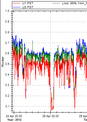
Flicker after STATCOM compensation
complication the the case was caused by a lot of switching activity in the surrounding electrical grid. This contributed to higher background flicker and making measurements more difficult. Finally, depending on the production type currently running, the flicker will vary.
STATCOM by AHF – the Solution
The solution was offered in cooperation with Schlatter AG, who also delivered the welding lines.
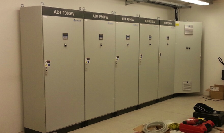
A STATCOM solution consisting of 7 300/690W water cooled active harmonic filters was installed. The nominal installed power is 2.5 MVAr. The fully water cooled STATCOM follows the load dynamically. Neither changes in the production nor newly installed equipment leads to any need for adjustment of the compensation system. The AHF units were installed via a dedicated transformer and use their own medium voltage measurement point.
Delivered Results
The STATCOM solution reduced the flicker level to Plt 0.6. Reduced reactive power lowered current consumption 25-40%. Voltage dips on the 20 kV rail were lowered from around 500V to around 100V.
