
Tagged: AHF
ABB literature FACT CHECK
We came across ABBs brochure for the ACS880 Ultra Low Harmonic and Regen Drives which is ABBs Active Front End solutions. We noted that someone has been very imaginative on a level where it is necessary to point it out. Surprising for such a well renown market leader.
What are we talking about?
Below is a snapshot from ABBs brochure for the ACS880 highlighting the incredible advantage of using Active Front End(AFE) drives instead of using passive or active filters. The main point being that the AFE has a much higher system efficiency than Active Harmonic Filters(AHF) and Passive Harmonic Filters(PHF) while maintaining a very high THD-reduction.
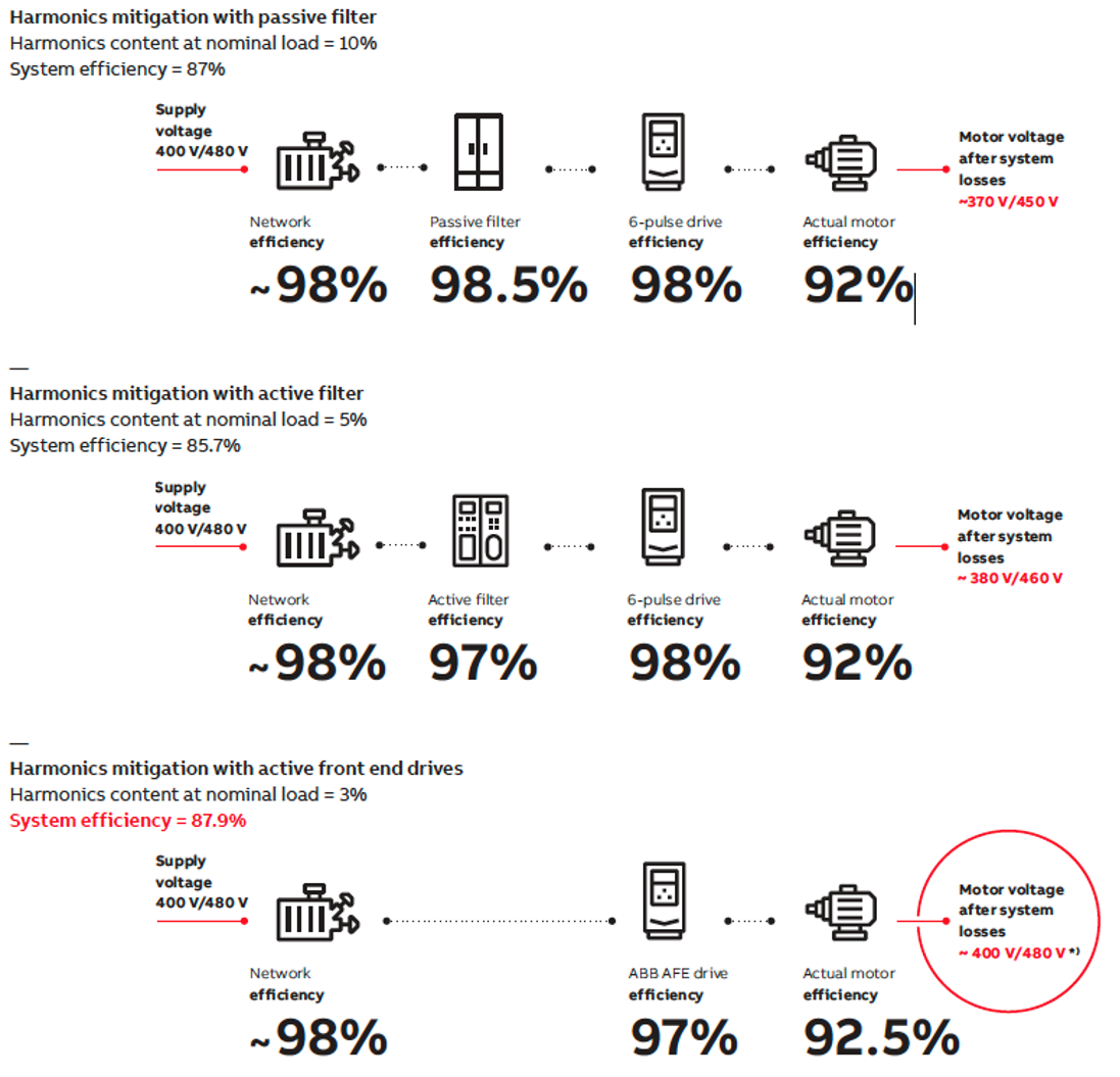
Figure 1: Snapshot from ABBs brochure in question.
So what is wrong?
Well, lets start with the AFE efficiency of 97%. Sounds fantastic, as an AFE is 2 x inverter +1x LCL filter it sounds incredible. Which it is. Theoretical losses should be roughly 2×1,2+2% so maximum 96,6%. There is an easier way to verify this and that is to actually check ABBs own datasheet for the ACS880.
An 250 kW ACS880-UHD has 11 kW losses through heat. That is 4.4% or an efficiency of 95.6% far from the 97% stated. To be fair a wall mounted 110 kW AFE is rated at 3.5% losses indicating 96.5% efficiency but still well below 97%.
So AFE system efficiency is 95.6-96.5% at optimum.
Secondly they are making a big deal that a 6-pulse drive create a significant voltage drop which in turn reduce the motor efficiency. Based on the numbers this must be an AC-choke they are using. Most drives are outfitted with DC-chokes with significantly less voltage drop. It is correct that a passive serial filter cause a voltage drop. An Active Filter being placed in parallel does not cause a voltage drop.
So, once again lets go back to the ACS880 6p version which is equipped with a dc-choke as standard. A 250 kW 6 P ACS 880 has 1,7-2,4% losses (wall/cabinet). So 98% is a good average.
Thirdly, most blatantly to us Active Filter Aficionados they have placed the Active Filter in a serial configuration!? Thus assuming that the Active Filter is sized 100% to load just like the Front End. In reality a typical active filter is placed in parallel with the load and sized based on the THD-load or roughly 25-33% of the load.
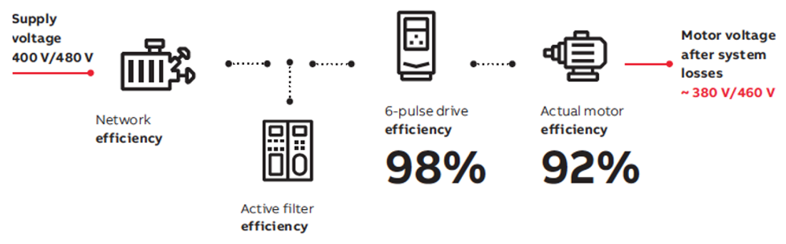
Figure 2: We helped ABB marketing correct the system topology. AHF sizing only focus on THD-level.
Using a Comsys ADF P100 as reference of an modern Active Harmonic Filter, it has 97.4% efficiency or 2.6% losses according to their datasheet.
So the AHF system losses will be 0.25-0.33 * 2.6 = 0.65-0.86% or 99.14-99.35% for simplicity we use AHF system size to be 30% of load or 99.22% system efficiency.
Updated system efficiencies:
Active Filter
Network Active Filter 6-P Drive Motor System Efficiency
98% 99.22% 98% 92%* 87.6%
*) The voltage drop across a 6P drive should be somewhere <6 V + any reactor loss if installed thus much smaller motor loss difference than suggested here. We do not have good data however and leave it as it is.
ACS 880 AFE
Network AFE Drive Motor System Efficiency
98% 95.6-96.5% 92.5% 86.7-87.5%
Difference AHF vs AFE = 0.9 -0.1 %
Conclusion
So the Active Filter Configuration system efficiency is actually on par or slightly better than the ACS880 at full load.
That is without AHF sleep mode, modularity and other complimentary solutions available to Active Filters. At part load things get even worse for the AFE but that is a story for another post.
Merus Power case study on EV-charging station

Segment background
The battery-operated truck industry has emerged as a transformative force within the transportation sector, offering a sustainable and eco-friendly solution to the longstanding challenges of heavy-duty vehicle emissions and fossil fuel dependency. These electric trucks, powered by advanced lithium-ion battery technology, are gaining momentum as an integral component of modern urban logistics and long-haul transportation. With the promise of zero-emission operation and significant reductions in operating costs over the long term, battery-operated trucks are not only aligned with environmental objectives but also represent a strategic choice for businesses aiming to optimize their fleet operations, comply with tightening emissions regulations, and contribute to a cleaner and more sustainable future for the global transportation industry.
Challenges at the customer’s facility
Driven by the need to comply with stringent grid code requirements, our customer recognized the necessity of improving power quality at their electric vehicle (EV) charging station. Specifically, they were facing challenges with harmonics, a common issue arising from the use of both AC and DC charging systems. The AC chargers, converting AC power to DC for the vehicles, were causing harmonic distortions in the electrical grid. DC fast chargers further compounded these harmonic problems, even introducing voltage fluctuations. To rectify these issues and meet grid code compliance, solutions like harmonic filters and active power factor correction were essential. Effective management of these harmonics is not only critical for maintaining the stability of the customer’s EV charging station but also impacts the integrity of the surrounding electrical infrastructure.
Our Merus® Solution
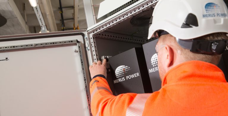
To address the harmonic issues in our customer’s EV charging station, the recommended solution is the use of Merus® A2 Active Harmonic Filters. Suggested and installed by our local partner, Power Capacitors Ltd, the Merus® A2 offers an efficient way to improve power quality. These filters are specifically designed to manage the harmonics introduced by both AC and DC chargers, thereby enhancing the system’s overall performance and reliability.
Incorporating Merus® A2 into the electrical setup involves its strategic placement to effectively reduce harmonic distortions from the charging units. By actively isolating and filtering out specific harmonic frequencies, the Merus® A2 contributes to improved power quality, reduced voltage distortions, and a more stable electrical grid. The IP31 design of Merus® A2 ensured a seamless and straightforward installation, aligning well with the site’s indoor setting and existing infrastructure.
Segment / Application
EV-charging station for battery operated trucks
Location
United Kingdom
Power quality issue
- High current harmonic distortion
Merus® Solution
Merus® A2 – Active Harmonic Filter
Merus® A2 is a scalable, versatile, and durable active harmonic filtering solution designed and manufactured in Finland using innovative Merus® technology.
Customer Benefits
- Grid code compliance
- Reduced wear and tear on electrical components
- Reduced maintenance costs
- Longer lifetime of sensitive electrical equipment
- Improved system efficiency
- Optimized performance of the charging system
Results after installation
Since installing the Merus® A2 Active Harmonic Filters, our customer’s EV charging station has experienced significant improvements, including reduced wear on electrical components and extended equipment life. These improvements have resulted in a more efficient system that not only complies with demanding grid codes but also contributes to a more sustainable electric vehicle charging infrastructure. The expertise provided by our local partner, Power Capacitors Ltd., was invaluable in achieving these outcomes.
The Merus® A2 Filters have effectively minimized the harmonic distortions originating from AC and DC chargers. This optimization has led to increased energy efficiency and lower maintenance costs. Thanks to these advancements, the customer’s EV charging station now operates with improved power quality and grid stability, fulfilling industry standards for both performance and sustainability.
Active Harmonic Filters Increase Productivity in the Paper Industry
AHF Compensates Thruster and Refrigeration Compressor
Danfoss used an Active Harmonic Filter to compensate the THD of their installed 960 kW of VFDs for thruster and refrigeration compressor on the fishing vessel Gitte Henning #8. The AHF ensured to keep the installation within class requirements. Read more at:
STATCOM Case Study
STATCOM AHF Reduces Flicker
Due to an increased usage of the local grid, a stricter limit of flicker emission became a necessity. One of the largest steel wire producers in Europe managed the problem by installing a STATCOM solution and lowering their flicker emissions.
Background

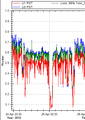
Flicker Before STATCOM Compensation
The processing plant is the largest steel wire producer in Europe, part of a German industry group founded in 1856. The company produces steel reinforcement mesh grids. The production line is made up of various welding equipment, including spot welders from Schlatter AG. As is the case with all powerful spot welders, the abrupt current consumption causes voltage variations, which in turn produces flicker.
Challenge
Due to expansion of the area and increased amount of renewable energy sources, it became necessary to lower flicker contribution. Early reference measurements showed flicker levels up to Pst 2 and Plt 1.4. A futher
Flicker after STATCOM compensation
complication the the case was caused by a lot of switching activity in the surrounding electrical grid. This contributed to higher background flicker and making measurements more difficult. Finally, depending on the production type currently running, the flicker will vary.
STATCOM by AHF – the Solution
The solution was offered in cooperation with Schlatter AG, who also delivered the welding lines.
A STATCOM solution consisting of 7 300/690W water cooled active harmonic filters was installed. The nominal installed power is 2.5 MVAr. The fully water cooled STATCOM follows the load dynamically. Neither changes in the production nor newly installed equipment leads to any need for adjustment of the compensation system. The AHF units were installed via a dedicated transformer and use their own medium voltage measurement point.
Delivered Results
The STATCOM solution reduced the flicker level to Plt 0.6. Reduced reactive power lowered current consumption 25-40%. Voltage dips on the 20 kV rail were lowered from around 500V to around 100V.
